4.1 Force on a Current Carrying Conductor in a Magnetic Field

  1. We have learned that when current flows in a conductor, a magnetic field will be generated.
  2. When the current-carrying conductor is placed in a magnetic field, the interaction between the two magnetic fields will produce a resultant field known as the catapult field as shown in the figure below.
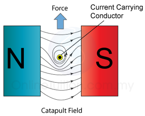
  1. The catapult field is a non-uniform field where the field at one side is stronger than the other side.
  2. As a result, a force is produced to move the current-carrying conductor from the stronger field to the weaker field.
  3. The force produced by a catapult field is called the catapult force.
  4. The direction of the force can be determined by Fleming’s left-hand rule as shown in Figure below.
  1. The forefinger, middle finger and the thumb are perpendicular to each other. The forefinger points along the direction of the magnetic field, middle finger points in the current direction and the thumb points along the direction of the force.
  2. The strength of the force can be increased by:
    1. Increase the current
    2. Using a stronger magnet
    3. using a longer wire
    4. arranging the wire perpendicular to the direction of the magnetic field.

Recommended Videos

Force on a current-carrying conductor in a magnetic field – Physics

External Resources

Physics Animation

Lorentz Force

External Link

XXX

4 Uses of Electromagnet – Telephone Earpiece

  1. An electromagnet is used in the earpiece of a telephone. The figure shows the simple structure of a telephone earpiece.
  2. When you speak to a friend through the telephone, your sound will be converted into electric current by the mouthpiece of the telephone.
  3. The current produced is a varying current and the frequency of the current will be the same as the frequency of your sound.
  4. The current will be sent to the earpiece of the telephone from your friend.
  5. When the current passes through the solenoid, the iron core is magnetised. The strength of the magnetic field changes according to the varying current.
  6. When the current is high, the magnetic field will become stronger and when the current is low, the magnetic field becomes weaker.
  7. The soft-iron diaphragm is pulled by the electromagnet and vibrates at the frequency of the varying current. The air around the diaphragm is stretched and compressed and produces sound wave.
  8. The frequency of the sound produced in the telephone earpiece will be the same as your sound.

4 Uses of Electromagnet – Electromagnetic Relay

  1. A relay is an electrical switch that opens and closes under the control of another electrical circuit.
  2. The switch is operated by an electromagnet to open or close one or many sets of contacts.
  3. A relay has at least two circuits. One circuit can be used to control another circuit. The 1st circuit (input circuit) supplies current to the electromagnet.
  4. When the switch is close, the electromagnet is magnetised and attracts one end of the iron armature.
  5. The armature then closes the contacts (2nd switch) and allows current flows in the second circuit.
  6. When the 1st switch is open again, the current to the electromagnet is cut, the electromagnet loses its magnetism and the 2nd switch is opened. Thus current stop to flow in the 2nd circuit.

4 Uses of Electromagnet – Electric Bell

  1. When the switch is on, the circuit is completed and current flows.
  2. The electromagnet becomes magnetised and hence attracts the soft-iron armature and at the same time pull the hammer to strike the gong. This enables the hammer to strike the gong.
  3. As soon as the hammer moves towards the gong, the circuit is broken. The current stops flowing and the electromagnet loses its magnetism. This causes the spring to pull back the armature and reconnect the circuit again.
  4. When the circuit is connected, the electromagnet regains its magnetism and pull the armature and hence the hammer to strike the gong again.
  5. This cycle repeats and the bell rings continuously.

Physics Animation
Applet
Simple Buzzer

Youtube Video

4 Magnetic Effects of a Current-Carrying Conductor – Solenoid

A solenoid is a long coil made up of a numbers of turns of wire.

Magnetic Field Pattern

  1. Figure (a) illustrates the field pattern produced by a solenoid when current pass through it.
  2. The field lines in the solenoid are close to each other, indicates that the magnetic field is stronger inside the solenoid.
  3. We can also see that the field lines are parallel inside the solenoid. This shows that the strength of the magnetic filed is about uniform inside the solenoid.
  4. We can also see that the magnetic field of a solenoid resembles that of the long bar magnet, and it behaves as if it has a North Pole at one end and a South Pole at the other.
(Figure (a): Magnetic field pattern of a solenoid)

Determining the Pole of the Magnetic Field

  1. The pole of the magnetic field of a solenoid can be determined by the Right Hand Grip Rule.
  2. Imagine your right-hand gripping the coil of the solenoid such that your fingers point the same way as the current. Your thumb then points in the direction of the field.
  3. Since the magnetic field lines always come out from the North Pole, hence the thumb points towards the North Pole.

[Figure (b)]

  1. There is another method can be used to determine the poles of the magnetic field forms by a solenoid.
  2. Try to visualise that you are viewing the solenoid from the 2 ends as illustrated in figure (c) below.
  3. The end will be a North pole if the current is flowing in the aNticlockwise, or a South pole if the current is flowing in the clockwiSe direction.

Strength of the Magnetic Field
The strength of the magnetic field can be increased by

  1. increasing the current,
  2. increasing the number of turns per unit length of the solenoid,
  3. using a soft-iron core within the solenoid.

4 Magnetic Effects of a Current-Carrying Conductor – Flat Coil

Field Pattern

  1. Figure (a) below shows the field pattern produced by a current flowing in a circular coil.
  2. In SPM, you need to know the field pattern, the direction of the field and the factors affect the strength of the field.
  3. The direction of the field can be determined by the Right-Hand Grip Rule. Grip the wire at one side of the coil with your right hand, with thumb pointing along the direction of the current. Your other fingers will be pointing in the direction of the field.
Figure (a)
  1. Figure (b) shows the plan view of the field pattern.

Factors affecting the strength
There are 3 ways to increase the strength of the magnetic field:

  1. increase the current and
  2. increase the number of turns of the coil.
  3. use coil with smaller radius

External Resources

Physics Animation

Magmatic Field of Current-Carrying Coil

External Link

XXX

4 Magnetics Effects of a Current Carrying Conductor – Straight Wire

Magnetic Field Pattern

(Figure (a))
  1. The magnetic field generated by a straight wire is concentric circles around the wire as shown in figure (a) above.
  2. Take notes that when the direction of the current is reversed, the direction of the magnetic field line is also reversed.
  3. The direction of the magnetic field line can be determined by Maxwell’s Screw Rule or the Right-Hand Grip Rule.
(Figure (b): The plan view of the magnetic field generated by a straight wire)
  1. Sometime, the magnetic field pattern may be given in plan view, as shown in figure (b).
  2. In plan view, a dot in the wire shows the current coming out from the plane whereas a cross in the wire shows the current moving into the plane.
(Figure (c): A dot indicates the current move out from a plane whereas a cross indicates the current move into the plane)

Direction of the Magnetic Field

The direction of the magnetic field formed by a current-carrying straight wire can be determined by the

  1. Right-Hand Grip Rule or the 
  2. Maxwell Screw Rule.

Right-Hand Grip Rule
Grip the wire with the right hand, with the thumb pointing along the direction of the current. The other fingers give the direction of the magnetic field around the wire. This is illustrated in the figure below.

(Figure (d))

The Maxwell’s Screw Rules
The Maxwell Screw Rules sometimes is also called Maxwell’s Corkscrew Rule. Imagine a right-handed screw being turned so that it bores its way in the direction of the current in the wire. The direction of rotation gives the direction of the magnetic field.

(Figure (e))

Strength of the Magnetic Field

  1. The strength of the magnetic field form by a current-carrying conductor depends on the magnitude of the current.
  2. A stronger current will produce a stronger magnetic field around the wire as shown in Figure (f) below.
    (Figure (f))
  3. The strength of the field decreases out as you move further out. This is illustrated in figure (g) below. Thus, you must be very careful when you are asked to draw the magnetic field in your exam.
    (Figure (g)
  4. The distance of the field lines must increase as it is further out from the wire.

4 Electromagnetism and Electromagnet

  1. When current passes through a conductor, the magnetic field will be generated around the conductor and the conductor becomes a magnet. This phenomenon is called electromagnetism. 
  2. Since the magnet is produced by electric current, hence it is called the electromagnet.
  3. An electromagnet is a type of magnet in which the magnetic field is produced by a flow of electric current. The magnetic field disappears when the current ceases.
  4. The magnetism of an electromagnet is switched on or off using electric current.
  5. In short, when current flow through a conductor, magnetic field will be generated. When the current ceases, the magnetic field disappears.

An electromagnet is a type of magnet in which the magnetic field is produced by a flow of electric current.

4 Introduction to Magnetism (Revision)

In form 3, we learned that

  1. a magnet can attract certain type of metal.
  2. the metals that can be attracted by a magnet are called the “magnetic materials” of “ferromagnetic materials”. Examples of magnetic materials are iron, steel, nickel and cobalt.
  3. a magnet has 2 poles-the North Pole and the South Pole.
  4. there is a magnetic field surrounding the magnet.  A magnetic field is a region in the surrounding of a magnet which a magnetic material experiences a detectable force.

Magnetic Field Line

(The magnetic field is represented by the magnetic field lines)
  1. The magnetic filed of a magnet is represented by the magnetic field lines. The magnetic field lines flow  out from the North pole and flow into the South pole.
  2. The distance between the field lines represent the strength of the field, the closer the field line, the stronger the field. In the diagram, the magnetic field A is stronger than magnetic field B because the line in magnetic field A is closer.

Compass in a Magnetic Field

(Figure(a): The pointer of a compass point towards the North pole of a magnet)


(Figure(b): The direction of the pointer of a magnet is always in the same direction of the magnetic field)
  1. The pattern and the direction of a magnetic field can be determined by a compass.
  2. First of all, we need to know that, in SPM, normally we use a circle with an arrow to represent compass. The arrow represents the pointer of a compass and it always points towards the North pole of a magnet.
  3. Second, we also need to know that the pointer of a compass is always in the direction of the magnetic field.
  4. In figure (b) above, we can see that when a few compasses are put near to a bar magnet, the pointer of the compasses are all in the direction of the magnetic field.
  5. If a compass is placed near to a current carrying wire, the pointer of the compass will point along the direction of the magnetic field generated by the current (as shown in the figure below). This will be discussed in electromagnetism.

External Resources

4 SPM Form 5 Chemistry Chapter 3 – Electromagnetism

  1. Introduction to Magnetism (Revision)
  2. Electromagnet
    1. Electric Bell
    2. Electromagnetic Relay
    3. Circuit Breaker
    4. Telephone Earpiece
    1. Straight Wire (Video 1)
    2. Flat Coil
    3. Solenoid
    4. Apllications of Electromagnet
  3. Force on a Current Carrying Conductor
    1. Moving Coil Meter
    2. Direct Current Motor
    3. Loud Speaker
    1. Turning Effect of a Current-Carrying Coil in a Magnetic Field
    2. Force between 2 Current Carrying Conductor
  4. Electromagnetic Induction
    1. DC Generator
    2. AC Generator (Video 1)
    1. Faraday’s Law and Lenz’s Law (Video 1)
    2. Induced EMF and Current in a Straight Wire
    3. Induced EMF and Current in a Solenoid
    4. Application of Electromagnetic Induction
    5. Direct Current and Alternating Current
    6. Root Mean Square Voltage/Current
  5. Transformer
    1. Types of Transformer and Their Calculation
    2. Factors Affect the Efficiency of a Transformer
  6. Generation and Transmission of Electricity
    1. Hydroelectric
    2. Fossil Fuel
    3. Solar Energy
    4. Nuclear Power
    5. Biomass Energy
    6. Wind Energy
    1. Sources of Energy Used to Generate Electricity
    2. Transmission of Electricity
    3. National Grid Network
  7. Intensive Notes
  8. Formulae List– Mind Map