4 Sources of Energy Used to Generate Electricity – Hydroelectric

Hydroelectric
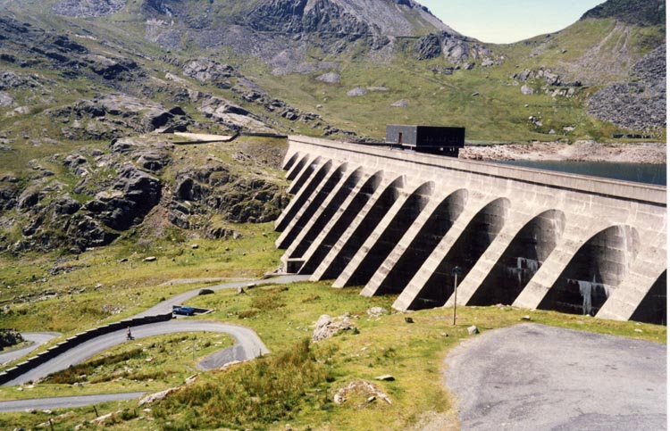
The advantages of using hydroelectric as a source of energy to generate electricity are.

  1. It is renewable energy.
  2. Building a dam does not pollute the environment.
  3. In a lot of countries, water can be easily obtained and is free.
  4. Building a hydroelectric plant does not involve very high technology as a nuclear power plant.

The disadvantages of using hydroelectric as a source of energy are.

  1. Building a dam will cause a large area flooded with water, and hence seriously destroys the ecosystem nearby.
  2. The flooded area causes the loss of wildlife habitat and agriculture land.
  3. Dam failure happens will cause a disaster to the lower reaches area of the river.
  4. The cost to build a dam is very high.

4 Uses of Electromagnet – Circuit Breaker

  1. The figure above shows the structure of a circuit breaker.
  2. A circuit breaker is an automatic switch that cut off current in a circuit when the current becomes too large.
  3. When the current in a circuit increases, the strength of the electromagnet will increase in accordance; this will pull the soft iron armature towards the electromagnet.
  4. As a result, the spring pulls apart the contact and disconnects the circuit immediately, and the current stop to flow.
  5. We can reconnect the circuit by using the reset button. The reset button can be pushed to bring the contact back to its original position to reconnect the circuit.

4 Law of Electromagnetic Induction

There are 2 principal laws of electromagnetic induction:

  1. Faraday’s law
  2. Lenz’s law

Faraday’s Law

  1. The magnitude of the induced e.m.f is determined by Faraday’s Law.
  2. Faraday’s Law states that the magnitude of the induced e.m.f is directly proportional to the rate of change of magnetic flux through a coil or alternatively the rate of the magnetic flux being cut.
  3. Therefore, the induced emf can be increased by
    1. using a stronger magnet
    2. increase the speed of the relative motion
    3. increase the number of turns of the coil

Lenz’s Law

  1. When a magnet is moved into and out of a coil, the induced current that flows through the coil can be determined from Lenz’s Law.
  2. Lenz’s Law states that the induced current always flows in the direction that opposes the change in magnetic flux.
  3. Lenz’s Law obeys the principle of conservation of energy. Work is done to move the magnet against the repulsive force. This work done is converted to electric energy which manifests as an induced current.
  4. For a conductor in a closed circuit moving perpendicular to a magnetic field and hence cutting its magnetic flux, the direction of the induced current is determined from Fleming’s Right-Hand Rule.
  5. Fleming’s Right-Hand Rule is used to determine the direction of the induced current that flows from the wire when there is relative motion with respect to the magnetic field

Physics Animation
Applet
Lenz’s Law – Molecular Expression

Kinetic Energy

Kinetic Energy
Kinetic energy is the energy of motion.

Equation of Kinetic Energy

Example
Determine the kinetic energy of a 2000-kg bus that is moving with a speed of 35.0 m/s.

Answer:

Kinetic Energy,

4.1 Force on a Current Carrying Conductor in a Magnetic Field

  1. We have learned that when current flows in a conductor, a magnetic field will be generated.
  2. When the current-carrying conductor is placed in a magnetic field, the interaction between the two magnetic fields will produce a resultant field known as the catapult field as shown in the figure below.
  1. The catapult field is a non-uniform field where the field at one side is stronger than the other side.
  2. As a result, a force is produced to move the current-carrying conductor from the stronger field to the weaker field.
  3. The force produced by a catapult field is called the catapult force.
  4. The direction of the force can be determined by Fleming’s left-hand rule as shown in Figure below.
  1. The forefinger, middle finger and the thumb are perpendicular to each other. The forefinger points along the direction of the magnetic field, middle finger points in the current direction and the thumb points along the direction of the force.
  2. The strength of the force can be increased by:
    1. Increase the current
    2. Using a stronger magnet
    3. using a longer wire
    4. arranging the wire perpendicular to the direction of the magnetic field.

Recommended Videos

Force on a current-carrying conductor in a magnetic field – Physics

External Resources

Physics Animation

Lorentz Force

External Link

XXX

4 Uses of Electromagnet – Telephone Earpiece

  1. An electromagnet is used in the earpiece of a telephone. The figure shows the simple structure of a telephone earpiece.
  2. When you speak to a friend through the telephone, your sound will be converted into electric current by the mouthpiece of the telephone.
  3. The current produced is a varying current and the frequency of the current will be the same as the frequency of your sound.
  4. The current will be sent to the earpiece of the telephone from your friend.
  5. When the current passes through the solenoid, the iron core is magnetised. The strength of the magnetic field changes according to the varying current.
  6. When the current is high, the magnetic field will become stronger and when the current is low, the magnetic field becomes weaker.
  7. The soft-iron diaphragm is pulled by the electromagnet and vibrates at the frequency of the varying current. The air around the diaphragm is stretched and compressed and produces sound wave.
  8. The frequency of the sound produced in the telephone earpiece will be the same as your sound.

4 Uses of Electromagnet – Electromagnetic Relay

  1. A relay is an electrical switch that opens and closes under the control of another electrical circuit.
  2. The switch is operated by an electromagnet to open or close one or many sets of contacts.
  3. A relay has at least two circuits. One circuit can be used to control another circuit. The 1st circuit (input circuit) supplies current to the electromagnet.
  4. When the switch is close, the electromagnet is magnetised and attracts one end of the iron armature.
  5. The armature then closes the contacts (2nd switch) and allows current flows in the second circuit.
  6. When the 1st switch is open again, the current to the electromagnet is cut, the electromagnet loses its magnetism and the 2nd switch is opened. Thus current stop to flow in the 2nd circuit.

4 Uses of Electromagnet – Electric Bell

  1. When the switch is on, the circuit is completed and current flows.
  2. The electromagnet becomes magnetised and hence attracts the soft-iron armature and at the same time pull the hammer to strike the gong. This enables the hammer to strike the gong.
  3. As soon as the hammer moves towards the gong, the circuit is broken. The current stops flowing and the electromagnet loses its magnetism. This causes the spring to pull back the armature and reconnect the circuit again.
  4. When the circuit is connected, the electromagnet regains its magnetism and pull the armature and hence the hammer to strike the gong again.
  5. This cycle repeats and the bell rings continuously.

Physics Animation
Applet
Simple Buzzer

Youtube Video

4 Magnetic Effects of a Current-Carrying Conductor – Solenoid

A solenoid is a long coil made up of a numbers of turns of wire.

Magnetic Field Pattern

  1. Figure (a) illustrates the field pattern produced by a solenoid when current pass through it.
  2. The field lines in the solenoid are close to each other, indicates that the magnetic field is stronger inside the solenoid.
  3. We can also see that the field lines are parallel inside the solenoid. This shows that the strength of the magnetic filed is about uniform inside the solenoid.
  4. We can also see that the magnetic field of a solenoid resembles that of the long bar magnet, and it behaves as if it has a North Pole at one end and a South Pole at the other.
(Figure (a): Magnetic field pattern of a solenoid)

Determining the Pole of the Magnetic Field

  1. The pole of the magnetic field of a solenoid can be determined by the Right Hand Grip Rule.
  2. Imagine your right-hand gripping the coil of the solenoid such that your fingers point the same way as the current. Your thumb then points in the direction of the field.
  3. Since the magnetic field lines always come out from the North Pole, hence the thumb points towards the North Pole.

[Figure (b)]

  1. There is another method can be used to determine the poles of the magnetic field forms by a solenoid.
  2. Try to visualise that you are viewing the solenoid from the 2 ends as illustrated in figure (c) below.
  3. The end will be a North pole if the current is flowing in the aNticlockwise, or a South pole if the current is flowing in the clockwiSe direction.

Strength of the Magnetic Field
The strength of the magnetic field can be increased by

  1. increasing the current,
  2. increasing the number of turns per unit length of the solenoid,
  3. using a soft-iron core within the solenoid.

4 Magnetic Effects of a Current-Carrying Conductor – Flat Coil

Field Pattern

  1. Figure (a) below shows the field pattern produced by a current flowing in a circular coil.
  2. In SPM, you need to know the field pattern, the direction of the field and the factors affect the strength of the field.
  3. The direction of the field can be determined by the Right-Hand Grip Rule. Grip the wire at one side of the coil with your right hand, with thumb pointing along the direction of the current. Your other fingers will be pointing in the direction of the field.
Figure (a)
  1. Figure (b) shows the plan view of the field pattern.

Factors affecting the strength
There are 3 ways to increase the strength of the magnetic field:

  1. increase the current and
  2. increase the number of turns of the coil.
  3. use coil with smaller radius

External Resources

Physics Animation

Magmatic Field of Current-Carrying Coil

External Link

XXX