4 Magnetics Effects of a Current Carrying Conductor – Straight Wire

Magnetic Field Pattern

(Figure (a))
  1. The magnetic field generated by a straight wire is concentric circles around the wire as shown in figure (a) above.
  2. Take notes that when the direction of the current is reversed, the direction of the magnetic field line is also reversed.
  3. The direction of the magnetic field line can be determined by Maxwell’s Screw Rule or the Right-Hand Grip Rule.
(Figure (b): The plan view of the magnetic field generated by a straight wire)
  1. Sometime, the magnetic field pattern may be given in plan view, as shown in figure (b).
  2. In plan view, a dot in the wire shows the current coming out from the plane whereas a cross in the wire shows the current moving into the plane.
(Figure (c): A dot indicates the current move out from a plane whereas a cross indicates the current move into the plane)

Direction of the Magnetic Field

The direction of the magnetic field formed by a current-carrying straight wire can be determined by the

  1. Right-Hand Grip Rule or the 
  2. Maxwell Screw Rule.

Right-Hand Grip Rule
Grip the wire with the right hand, with the thumb pointing along the direction of the current. The other fingers give the direction of the magnetic field around the wire. This is illustrated in the figure below.

(Figure (d))

The Maxwell’s Screw Rules
The Maxwell Screw Rules sometimes is also called Maxwell’s Corkscrew Rule. Imagine a right-handed screw being turned so that it bores its way in the direction of the current in the wire. The direction of rotation gives the direction of the magnetic field.

(Figure (e))

Strength of the Magnetic Field

  1. The strength of the magnetic field form by a current-carrying conductor depends on the magnitude of the current.
  2. A stronger current will produce a stronger magnetic field around the wire as shown in Figure (f) below.
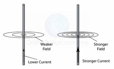
    (Figure (f))
  3. The strength of the field decreases out as you move further out. This is illustrated in figure (g) below. Thus, you must be very careful when you are asked to draw the magnetic field in your exam.
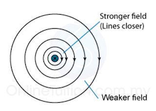
    (Figure (g)
  4. The distance of the field lines must increase as it is further out from the wire.

4 Electromagnetism and Electromagnet

  1. When current passes through a conductor, the magnetic field will be generated around the conductor and the conductor becomes a magnet. This phenomenon is called electromagnetism. 
  2. Since the magnet is produced by electric current, hence it is called the electromagnet.
  3. An electromagnet is a type of magnet in which the magnetic field is produced by a flow of electric current. The magnetic field disappears when the current ceases.
  4. The magnetism of an electromagnet is switched on or off using electric current.
  5. In short, when current flow through a conductor, magnetic field will be generated. When the current ceases, the magnetic field disappears.

An electromagnet is a type of magnet in which the magnetic field is produced by a flow of electric current.

4 Introduction to Magnetism (Revision)

In form 3, we learned that

  1. a magnet can attract certain type of metal.
  2. the metals that can be attracted by a magnet are called the “magnetic materials” of “ferromagnetic materials”. Examples of magnetic materials are iron, steel, nickel and cobalt.
  3. a magnet has 2 poles-the North Pole and the South Pole.
  4. there is a magnetic field surrounding the magnet.  A magnetic field is a region in the surrounding of a magnet which a magnetic material experiences a detectable force.

Magnetic Field Line

(The magnetic field is represented by the magnetic field lines)
  1. The magnetic filed of a magnet is represented by the magnetic field lines. The magnetic field lines flow  out from the North pole and flow into the South pole.
  2. The distance between the field lines represent the strength of the field, the closer the field line, the stronger the field. In the diagram, the magnetic field A is stronger than magnetic field B because the line in magnetic field A is closer.

Compass in a Magnetic Field

(Figure(a): The pointer of a compass point towards the North pole of a magnet)


(Figure(b): The direction of the pointer of a magnet is always in the same direction of the magnetic field)
  1. The pattern and the direction of a magnetic field can be determined by a compass.
  2. First of all, we need to know that, in SPM, normally we use a circle with an arrow to represent compass. The arrow represents the pointer of a compass and it always points towards the North pole of a magnet.
  3. Second, we also need to know that the pointer of a compass is always in the direction of the magnetic field.
  4. In figure (b) above, we can see that when a few compasses are put near to a bar magnet, the pointer of the compasses are all in the direction of the magnetic field.
  5. If a compass is placed near to a current carrying wire, the pointer of the compass will point along the direction of the magnetic field generated by the current (as shown in the figure below). This will be discussed in electromagnetism.

External Resources

4 SPM Form 5 Chemistry Chapter 3 – Electromagnetism

  1. Introduction to Magnetism (Revision)
  2. Electromagnet
    1. Electric Bell
    2. Electromagnetic Relay
    3. Circuit Breaker
    4. Telephone Earpiece
    1. Straight Wire (Video 1)
    2. Flat Coil
    3. Solenoid
    4. Apllications of Electromagnet
  3. Force on a Current Carrying Conductor
    1. Moving Coil Meter
    2. Direct Current Motor
    3. Loud Speaker
    1. Turning Effect of a Current-Carrying Coil in a Magnetic Field
    2. Force between 2 Current Carrying Conductor
  4. Electromagnetic Induction
    1. DC Generator
    2. AC Generator (Video 1)
    1. Faraday’s Law and Lenz’s Law (Video 1)
    2. Induced EMF and Current in a Straight Wire
    3. Induced EMF and Current in a Solenoid
    4. Application of Electromagnetic Induction
    5. Direct Current and Alternating Current
    6. Root Mean Square Voltage/Current
  5. Transformer
    1. Types of Transformer and Their Calculation
    2. Factors Affect the Efficiency of a Transformer
  6. Generation and Transmission of Electricity
    1. Hydroelectric
    2. Fossil Fuel
    3. Solar Energy
    4. Nuclear Power
    5. Biomass Energy
    6. Wind Energy
    1. Sources of Energy Used to Generate Electricity
    2. Transmission of Electricity
    3. National Grid Network
  7. Intensive Notes
  8. Formulae List– Mind Map

Gravity

Gravitational Field

A gravitational field as a region in which an object experiences a force due to gravitational attraction.

Gravitational Field Strength

  1. The gravitational field strength at a point in the gravitational field is the gravitational force acting on a mass of 1 kg placed at that point.
  2. The unit of gravitational field strength is N/kg.
  3. The gravitational field strength is denoted by the symbol “g”. g= F m g = Gravitational Field Strength
    F = Force acted on an object
    m = mass of the object.

Gravitational Acceleration

  1. The gravitational acceleration is the acceleration of an object due to the pull of the gravitational force.
  2. The unit of gravitational acceleration is ms-2
  3. Gravitational acceleratio is also denoted by the symbol “g”.

Important notes:

  1. Gravitational acceleration does not depend on the mass of the moving object.
  2. The magnitude of gravitational acceleration is taken to be 10ms-2.

    Gravitational Field Strength vs. Gravitational Acceleration

    1. Both the gravitational field strength and gravitational acceleration have the symbol, g and the same value (10ms-2) on the surface of the earth.
    2. When considering a body falling freely, the g is the gravitational acceleration.
    3. When considering objects at rest, g is the Earth’s gravitational field strength acting on it.

    Weight

    1. The weight of an object is defined as the gravitational force acting on the object.
    2. The SI unit of weight is Newton (N)

    Differences between Weight and Mass

    Weight Mass
    Depends on the gravitational field strength Independent from the gravitational field strength
    Vector quantity Scalar Quantity
    Unit Newton (N) Unit: Kilogram (kg)

    3 SPM Form 5 Physics Mind Map Formulae List – Chapter 2

    Click on the image to enlarge.

    The images above shows the formulae that students need to know in Malaysia SPM Physics syllabus in Mind Map form. You may click on the image to enlarge it for a better view. You may also download and print it out for further reference.

    Electricity is the second chapter in SPM Form 5 Physics. There are a lot of formulae in this chapter, and most of them look similar. In order to answer the calculation questions, you must understand how the potential difference and current change in a circuit.

    Please share it with your friends if you found it useful.

    3 Series Circuit and Parallel Circuit

    Series Circuit and Parallel Circuit

    1. The resistors connected in one non-branched wire is said to be connected in series, whereas resistors connected in a branched wire is said to be connected in parallel.
    2. In the diagram above, (a), (b) and (c) are series circuit whereas (d), (e) (f) and (g) are parallel circuit.

    3.1 Electric Field

    Electric Field


    1. An electric field is a region in which an electric charged particle experiences an electric force.
    2. Electric field is represented by a number of lines with arrows, called electric lines of force or electric field lines.
    3. The direction of the field at a point is defined by the direction of the electric force exerted on a positive test charge placed at that point.
    4. The strength of the electric field is indicated by how close the field lines are to each other. The closer the field lines, the stronger the electric field in that region.
      Example
    5. The lines of force are directed outwards for a positive charge and inwards for a negative charge.
    6. The electric line of force will never cross each other.
    7. The figure shows a few examples of the field pattern that you need to know in the SPM syllabus.

    Effect of Electric Field on a Ping Pong Ball Coated with Conducting Material


    1. A ping ball coated with conducting material is hung by a nylon thread.
    2. When the ping pong ball is placed in between 2 plates connected to a Extra High Tension (E.H.T.) power supply, opposite charges are induced on the surface of the ball. The ball will still remain stationary. This is because the force exert on the ball by the positive plate is equal to the force exerted on it by the negative plate.
    3. If the ping pong ball is displaced to the right to touch the positive plate, it will then be charged with positive charge. Since like charges repel, the ball will be pushed towards the negative plate.
    4. When the ping pong ball touches the negative plate, it will be charged with negative charge. Again, like charge repel, the ball will be pushed towards the positive plate. This process repeats again and again, causes the ping pong ball oscillates to and fro continuously between the two plates.

    A Candle Flame in an Electric Field


    1. Normally, with absent of wind, the flame of a candle is symmetry.
    2. The heat of the candle flame removes electrons from the air molecules around it, and therefore ionised the molecule. As a result, the flame is surrounded by a large number of positive and negative ions.
    3. If the candle is placed in between 2 plates connected to a Extra High Tension (E.H.T.) power supply, the positive ions will be attracted to the negative plate while the negative ions will be attracted to the positive plate.
    4. The spreading of the flame is not symmetry. This is because the positive ions are much bigger than the negative ions; it will collide with the other air molecule and bring more air molecule towards the negative plate.

    3 Electric Charge

    Electric Charge

    1. There are two kinds of electric charge, namely the positive charge and the negative charge.
    2. Like charge repel each other.
    3. Unlike charge attract each other.
    4. A neutral body can be attracted by another body which has either a positive or negative charge.
    5. The SI unit of electric charge is Coulomb (C).
      Example
      Charge of 1 electron = -1.6 x 10⁻¹⁹C
      Charge of 1 proton = +1.6 x 10⁻¹⁹C
    6. A Van de Graaff generator can be used to generate charges.
    7. Materials that allow electrons to pass through them are conductors.
    8. Charged conductors become neutral when they are earthed.

    Charge and Relative Charge

    Sum of Charge

    Sum of charge
    = number of charge particles × charge of 1 particle

    Q=ne

    Example:
    Find the charge of 2.5 x 10¹⁹ electrons.
    (Charge of 1 electron is   -1.6 x 10⁻¹⁹C)

    Answer:
    Number of electrons, n = 2.5 x 10¹⁹
    Charge of 1 electron, e = -1.6 x 10⁻¹⁹C
    Q=ne
    Q=(2.5× 10¹⁹ )(−1.6× 10⁻¹⁹ )
    Q=−4C

    3 SPM Form 5 Physics Chapter 2 – Electricity

    1. Fundamental of Electricity
      1. Electric Charge
      2. Electric Field
      3. Effect of Electric Field
        1. Effect of Electric Field on a Ping Pong Ball Coated with Conducting Material
        2. A Candle Flame in an Electric Field
      4. Current
      5. Potential and Potential Difference
        1. Relationship Between Current and Potential Difference
        2. Resistance
    2. Series Circuit and Parallel Circuit
      1. Resistance in series and parallel Circuit
        1. Comparing the resistance in series/parallel/combine circuit
        2. Finding the resistance of an individual resistor
      2. Current in a Circiut
      3. Potential and Potential Difference in a Circuit
      4. Finding Current in a Series Circuit
      5. Finding Current in a Parallel Circuit
      6. Finding Potential Difference in a Series Circuit
    3. Electromotive Force
      1. Difference between Electromotive Force and Potential Difference
      2. Internal Resistance and Potential Difference Drop
      3. Measuring e.m.f. and Internal Resistance
        1. Open Circuit/Close Circuit
        2. Simultaneous Equation
        3. Linear Graph
    4. Electrical Energy, Power and Efficiency
      1. Electrical Energy
      2. Electrical Power
        1. Sum of the Power
        2. Power Rating
        3. Energy Consumption
      3. Efficiency of Electrical Appliance
      4. Steps to Save Electricity

    Objective Questions

    1. Electric Charge and Field (6 Questions)
    2. Current (7 Questions)
    3. Potential Difference (5 Questions)
    4. Ohm’s Law and Resistivity (7 Questions)
    5. Understanding Circuit – Resistance (7 Questions)
    6. Circuit – Current (4 Questions)
    7. Circuit – Potential Difference (6 Questions)
    8. Electromotive Force (7 Questions)
    9. Electrical Energy and Power (7 Questions)