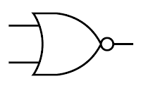
Symbol of the Logic Gate
For each gate, the input or inputs are on the left of the symbol. The output is on the right
The Truth Tables
- The function of a logic gate can be shown by using the Truth tables.
- A truth table lists all possible input together with the corresponding output.
AND gate
Symbol:
Boolean Expression:
X=A•B
Truth Table:
| Truth Table | ||
| INPUT | OUTPUT | |
| 0 | 0 | 0 |
| 0 | 1 | 0 |
| 1 | 0 | 0 |
| 1 | 1 | 1 |
Notes:
The output is HIGH (1) only if both the inputs are HIGH (1).
OR gate
Symbol:
Boolean Expression:
X=A+B
Truth Table:
| Truth Table | ||
| INPUT | OUTPUT | |
| 0 | 0 | 0 |
| 0 | 1 | 1 |
| 1 | 0 | 1 |
| 1 | 1 | 1 |
Notes:
The output is HIGH (1) only if one or more inputs are HIGH (1).
NOT gate
Symbol:
Boolean Expression:
X= A ¯
Truth Table:
| Truth Table | ||
| INPUT | OUTPUT | |
| 0 | 1 | |
| 1 | 0 | |
Notes:
The output is the opposite of the input.
NAND gate
Symbol:
Boolean Expression:
X= A•B ¯
Truth Table:
| Truth Table | ||
| INPUT | OUTPUT | |
| 0 | 0 | 1 |
| 0 | 1 | 1 |
| 1 | 0 | 1 |
| 1 | 1 | 0 |
Notes:
The output is LOW (0) only if both the inputs are HIGH (1).


