5 Structured Questions – Cathode Ray Oscilloscope

Diagram \(4.1\) shows a bright spot, P, formed on the screen of a cathode-ray oscilloscope, C.R.O. when it is switched on.

  1. What is the meaning of cathode ray? [1 mark]
    High speed election beam.
  2. Explain how the bright spot is formed on the screen of the C.R.O. [2marks]
    When the electrons hit the fluorescent screen, the screen glows and forms a light spot. The kinetic energy of the electrons changes to light energy.
  3. Diagram \(4.2\) shows the bright spot is displaced to \(Q\) when a direct current, d.c. supply, is connected to the Y-input of the C.R.O.

The Y-gain of the C.R.O is set at \(2 V /\) division. Calculate the input voltage of the d.c. supply. [2 marks]

Output voltage
\[
\begin{aligned}
&=2 V +2 V \\
&=4 V
\end{aligned}
\]

  1. Diagram \(4.3\) shows an alternating current, a.c. supply, is connected to the C.R.O. The Y-gain of the C.R.O. remains at \(2 V /\) division.

Draw the output signal on the screen in Diagram \(4.3\) when the peak voltage of the a.c. supply is \(6 V\) and the time base is switched off. [2 marks]

5 SPM Form 5 Physics Mind Map Formulae List – Chapter 4

Click on the image to enlarge.

The image above shows the formulae that students need to know in Malaysia SPM Physics syllabus in Mind Map form. You may click on the image to enlarge it for a better view. You may also download and print it out for further reference.

Please share it with your friends if you found it useful.

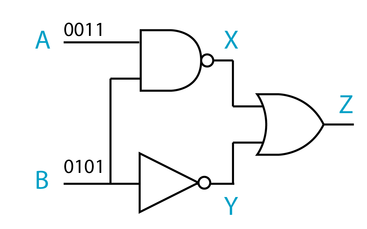
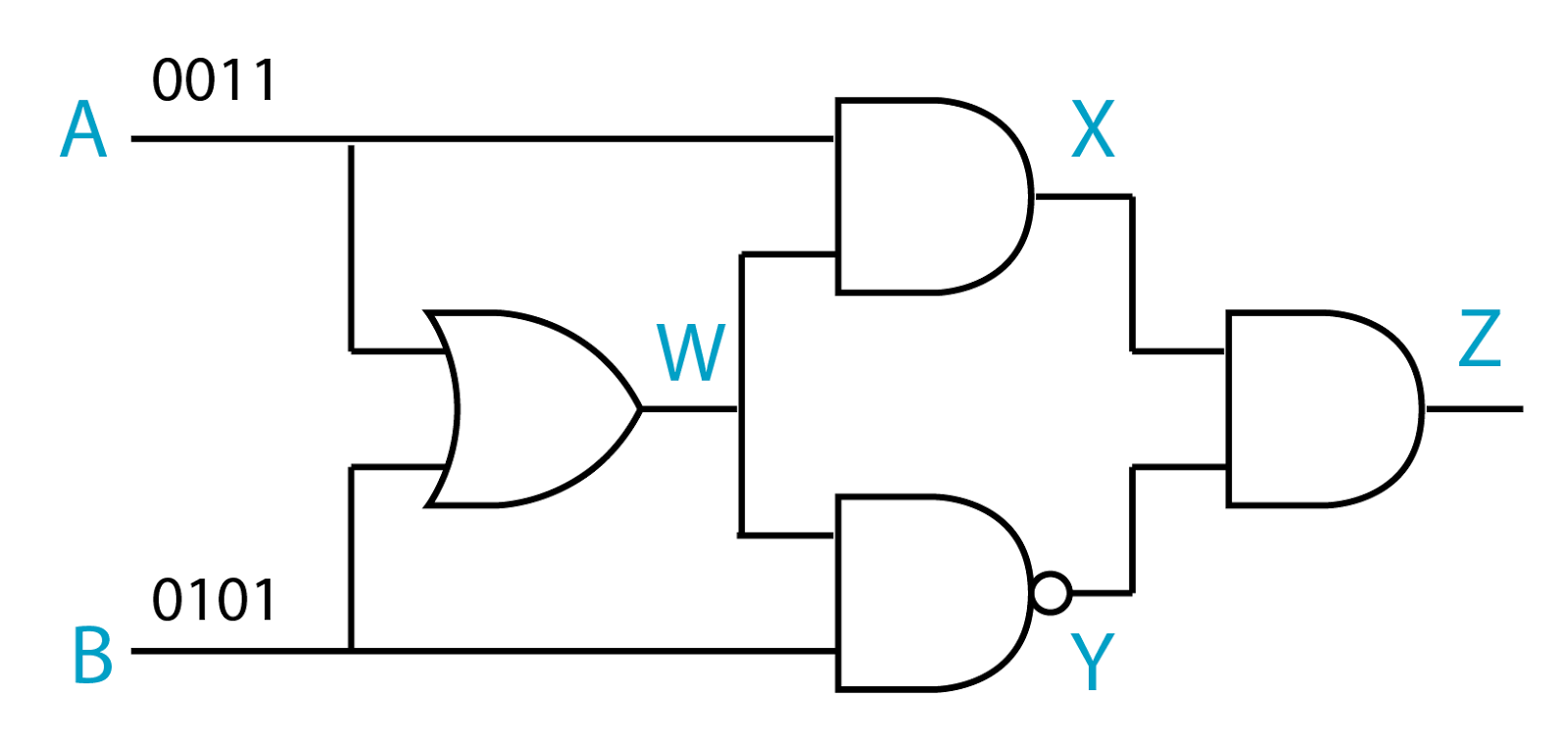
Electronics is the 4th chapter of SPM Form 5 Physics. There is almost no calculation questions in this chapter. The question related to speed of electrons seldom come out in exam. The question related to transistor may come out occasionally in paper 2. In order to answer the question, you must understand the concept of potential divider.

5 Logic Gates – Combination of Logic Gate

  1. Logic gates can be combined together to perform certain tasks.
  2. The output can be determined by constructing a truth table.

Example 1:

In the combination of logic gates above, find the outputs X, Y and Z of the inputs A and B.
Answer:

INPUTOUTPUT
ABXYZ
00111
01101
10111
11000

Example 2:

In the combination of the logic gate above, find the outputs X, Y and Z of the inputs A and B.
Answer:

INPUTOUTPUT
ABXYZ
00111
01101
10011
11000

Example 3:

In the combination of the logic gate above, find the outputs X, Y and Z of the inputs A and B.
Answer:

INPUTOUTPUT
ABWXYZ
000010
011000
101100
111100

Example 4:

In the combination of the logic gate above, find the outputs X, Y and Z of the inputs A and B.
Answer:

INPUTOUTPUT
ABWXYZ
000011
011000
101000
111101

5 Logic Gates – Symbol, Boolean Algebra and Truth Table

Symbol of the Logic Gate

For each gate, the input or inputs are on the left of the symbol. The output is on the right

The Truth Tables

  1. The function of a logic gate can be shown by using the Truth tables.
  2. A truth table lists all possible input together with the corresponding output.

AND gate

Symbol:

Boolean Expression:
X=A•B
Truth Table:

Truth Table
INPUTOUTPUT
000
010
100
111

Notes:
The output is HIGH (1) only if both the inputs are HIGH (1).

OR gate

Symbol:

Boolean Expression:
X=A+B
Truth Table:

Truth Table
INPUTOUTPUT
000
011
101
111

Notes:
The output is HIGH (1) only if one or more inputs are HIGH (1).

NOT gate

Symbol:

Boolean Expression:
X= A ¯
Truth Table:

Truth Table
INPUTOUTPUT
01
10

Notes:
The output is the opposite of the input.

NAND gate

Symbol:

Boolean Expression:
X= A•B ¯
Truth Table:

Truth Table
INPUTOUTPUT
001
011
101
110

Notes:
The output is LOW (0) only if both the inputs are HIGH (1).

NOR gate

Symbol:

Boolean Expression:
X= A+B ¯
Truth Table:

Truth Table
INPUTOUTPUT
001
010
100
110

Notes:
The output is HIGH (1) only if both the inputs are LOW (0).

5 Logic Gates

  1. A logic gate is a physical device that performs a logical operation on one or more logical inputs and produces only one logical output.
  2. The input is the signal or data that fed into a logic gate whereas the output is the result of processing the inputs by using the operation of the logic gate.
  3. The input and output can be either high (denoted by 1) or low (denoted by 0).
  4. Gates are identified by their function. The 5 basic logic gates that you need to know under SPM syllabus are
    1. the AND gate
    2. the OR gate
    3. the NOT gate
    4. the NAND gate
    5. the NOR gate
  5. Logic gates primarily work using diodes and transistors as switches. 

5 Uses of Cathode Ray Oscilloscope

Uses of Cathode Ray Oscilloscope

In a laboratory, a cathode ray oscilloscope can be used to

  1. display different types of waveform. 
  2. measure short time interval
  3. measure potential difference (as a voltmeter)

Displaying Wave Forms

  1. A cathode-ray oscilloscope can be used to display different types of waveform by connecting a power supply to the Y-input. 
  2. The figure below shows a few types of waveform displays on an oscilloscope.

Click on the links below for a discussion about measuring short time interval and measuring the potential difference

  1. Measuring Short Time Interval
  2. Measuring Potential Difference

Measuring Potential Difference

  1. In order to measure the potential difference, we need to move the bright spot to the centre before the Y-input is connected to any circuit.
  2. We also need to set the Y-gain. However, this can be adjusted later so that the signal can be fully displayed on the screen.
  3. The potential to be measured is then applied to the Y-plates via the Y-input terminals. 

Measuring Potential Difference of a Direct Current

  1. The time-base is switched off. When a potential difference is applied to the Y-input, an electric field is set up between the plates. This will deflect the cathode ray either up or down.
  2. The deflection of the electron beam by an electric field is proportional to the voltage applied. The reading of the voltage can be determined by referring to the Y-gain.
  3. For example, in the figure above, if the Y-gain is set to 2V per division (2V/div), then the reading of the potential difference is 4V.
  4. If the terminal of the direct current is inverted, the bright spot will be deflected to the opposite side, as shown in the diagram below. The reading of the potential difference will remain the same (4V).

Effect of the Y-gain

Figure below shows the display of the CRO when the Y-gain is set to 1V/div and 5V/div respectively for a potential difference of 4V.
(Click on the image to enlarge)

Effect of the Time Base

  1. The time base move the bright spot across the screen at a constant speed.
  2. Usually, the speed is very high. As a result, we are not able to see the motion of the bright spot, but a straight line across the screen.
  3. Figure below shows the display of a CRO when the time base is ON and OFF.

Measuring Potential Difference of an Alternating Current

  1. If an alternating current is connected to the Y-input, a changing potential difference will be applied between the Y-plates.
  2. The changing potential difference will move the bright spot up and down continuously.
  3. As a result, vertical straight line will form on the screen of the CRO. The reading of the potential difference can be determined by referring to the Y-gain.
  4. For example, for the diagram above, if the Y-gain is set to 2V/div, then the maximum potential difference (peak voltage) is 4V.

Effect of the Time Base

  1. If the time base is switched on, it will move the bright spot across the screen horizontally.
  2. The result of the vertical motion caused by the Y-plate and the horizontal motion caused by the time base is a sinusoidal wave form.
  3. Diagram below shows the CRO display when the time base is on and off.

Measuring Short Time Interval

  1. A cathode ray oscilloscope can be used to determined the time interval between 2 pulses, even though the time interval is very small.
  2. Figure above shows 2 pulses on the screen of a cathode ray oscilloscope.
  3. If the time base is set to 2 ms/div, the time interval between the 2 pulses can be calculated as follow:
t = 6 x 2ms = 12 ms = 0.012s.

Displaying Wave Forms


  1. A cathode ray oscilloscope can be used to display different types of waveform by connecting a power supply to the Y-input. 
  2. Figure below shows a few types of waveform displays on an oscilloscope.

5 Using Cathode Ray Oscilloscope

Using CRO

Function
 1. Power switch To switch on and off of the oscilloscope
2. Focus controlTo control the focus of the spot on the screen.
3. Intensity controlTo control the brightness of the spot on the screen.
4. X-offset
5. Y-offset
Y-offset moves the whole trace vertically up and down on the screen, while X-offset moves the whole trace from side to side on the screen.
6. Timebase control

Whenever we switch on the time-base, we are actually applying a sawtooth voltage to the X-plates (Figure below).

* This makes the electron beam sweep across the screen at a constant speed.
* By knowing the period of each cycle, T, we can then know how fast the beam is sweeping across the screen. The time-base is thus a measure of time for the oscilloscope.

7. Y gain control* the “Volts/Div.” wheels amplify an input signal so that for a division a given voltage level is invalid. A “division” is a segment, a square on the screen of the oscilloscope.
* A setting of “.5” i.e. means, that the height of a single square equals a voltage of 0.5 V. An amplitude of 1 V would have a size of two divisions vertical to the abscissa.
8. d.c./a.c. switchd.c. – d.c. and a.c. voltage displayed.
a.c. – only a.c. voltage displayed.
9. X-input and Y-inputElectric input connects to the X-plate and Y-plate.

Example
The table below shows the sample display of direct current and alternating current when the time base is switched ON and OFF.

 Direct Current (Time Base Switched Off) Direct Current (Time Base Switched On)
 Alternating Current (Time Base Switched Off) Alternating Current (Time Base Switched On)

5 Structure of Cathode Ray Oscilloscope

The cathode-ray oscilloscope (C.R.O.) consists of the following components:

  1. The electron gun.
  2. The deflecting plates.
  3. A fluorescent screen.

The electron gun

Parts of Electron GunFunction
 Filament To heat the cathode.
 Cathode Release electrons when heated by filament.
 Grid
  •  The grid is connected to a negative potential. The more negative this potential, the more electrons will be repelled from the grid and fewer electrons will reach the anode and the screen.
  • The number of electrons reaching the screen determines the brightness of the light. Hence, the negative potential of the grid can be used as a brightness control.
 Focusing Anode and
  •  The other feature in the electron gun is the use of the anode.
  • The anode at positive potential accelerates the electrons and the electrons are focused into a fine beam as they pass through the anode.
 Accelerating anode

The deflecting plates

Part of the deflecting systemFunction
 Y-plateThe Y-plates will cause deflection in the vertical direction when a voltage is applied across them.
  X-plate On the other hand, the X-plates will cause the electron beam to be deflected in the horizontal direction if a voltage is applied across them.

The fluorescent screen

  1. The screen is coated with a fluorescent salt, for example, zinc sulphide.
  2. When the electrons hit the screen, it will cause the salt to produce a flash of light and hence a bright spot on the screen.

5.1 Thermionic Emission

Thermionic Emission

  1. Thermionic emission is a process of emission of charged particles (known as thermion) from the surface of heated metal.
  2. The charge particles normally are electrons.
  3. The rate of emission (number of electrons emitted in 1 second) is affected by 4 factors, namely
    1. the temperature of the heated metal,
      When the temperature of the metal increase, the emission rate of electrons will increase.
    2. the surface area of the heated metal,
      When the surface area of the metal increase, the emission rate of electrons will increase.
    3. the types of metal
      The rates of thermionic emission are different with regard to different types of metals.
    4. the coated material on the surface of the metal.
      If the surface is coated by a layer of barium oxide or strontium oxide, the rate of emission will become higher.

Thermionic Diode

  1. Thermionic emission is applied in a thermionic diode.
  2. A diode is an electrical component that only allowed current flows in one direction.
  3. The figure below shows the illustration of a thermionic diode.
  4. Electrons can only be released from the tungsten filament (when it is hot) and move toward the anode which is connected to the positive terminal.
  5. Electrons are not allowed to move in the opposite direction because no electrons will be released from the anode.
  6. As such, the electrons can only move from left to right but not the other way round.

5 Cathode Ray Oscilloscope

Cathode Ray Oscilloscope

(Cathode Ray Tube Television)
  1. Cathode-ray tubes have become part of everyday life.
  2. They can be found in the screens of television sets and computer monitors.
  3. In the Physics laboratory, we use the cathode-ray tube in the oscilloscope to study waveforms.
  4. In SPM, you need to know
    1. How cathode ray is produced (Thermionic emission and electron gun)
    2. The characteristics of cathode ray (Study by using the Maltese Cross Tube and Deflection Tube).
    3. the structure of a Cathode Ray Oscilloscope
    4. how to operate a Cathode Ray Oscilloscope
    5. the uses of a Cathode Ray Oscilloscope
(Cathode Ray Oscilloscope)